v0.3
Made a few more changes to my solar rig – after discovering a few issues with the original design and figuring out a solution for them – and in the process I learned about diodes, Ferrite cores, EMI filters, circuit breakers and fuses.
It all started after watching this video on youtube: https://www.youtube.com/watch?v=pT3rr4c9_u4
Battery bank changes:
After looking into a few extra safety measures others have put in place for their solar systems I decided I wanted to add fuses to each battery connection and to connect all my batteries in a way in which it would also allow me to disconnect them from the system without needing to disconnect the batteries.
What I ended up doing was to add a 12V 25A fuse to the positive wire of each battery and connect all batteries in parallel to bus bars only the bar was not a bar … more like a thick cable which does pretty much the same thing but is flexible.
After watching that youtube video and noticing how he wired the two controllers to the same inverter I realized my mistake with previous design. By having a diode in place you ensure current flows in the correct direction rather than having one controller pushing juice to the other one (which in my case ruined two solar controllers without me realizing why …)
An EMI filter helps filter out bad currents (lightning storms cause electro magnetic interference, same thing is valid for radio waves – think mobile phones, etc, not to mention other devices like compressors – think fridge) and the Ferrite core does some magic on the current itself effectively altering the sinewave … need to link something here
Also, another thing I realized, is the fact that a bad battery can seriously mess with your setup (by draining juice from the other batteries) and because in my rig I have a few of those I decided I need to do something about that so I wired them separately.
Another important thing to have is grounding – one needs to make sure the solar panels are wired to ground (in case lightning strikes) and also the inverter should be grounded. Some also suggest wiring the battery bank(s) to the ground, others seem to suggest otherwise BUT if you decide to do such a thing make sure you wire the negative pole of the battery bank to the ground AND make sure you don’t share the same grounding wire with the other side of the circuit (AC) because that could cause more problems.
v0.4
Unfortunately I completely forgot about v0.3 article above (I mean I prepared it a while ago but forgot to draw it) so now I’m going to add the missing bits to get to the current version.
The previous rig worked well however due to me wiring some crappy chinese ATS devices to it I managed to short it a few times until I fried the inverter I had (ATS – automatic transfer switch – turns out these are good to use in manual mode but not so good in automatic mode … ) and because of that I decided to ditch them and to go searching for another interver only this time I figured let’s try to find fancier one and when I landed on this link:
i simply could not help myself 🙂
To make things ever more safe I decided to install this bad boy taking into account the recommendations I found in its manual so I mounted it on a panel (painted with fire retardant paint), I left some room to its sides for cooling, I wired a 50Amp fuse between it and the PV as well as a 100Amp fuse between it and the battery bank, I linked the ground to the negative pole of the battery bank and tidied up the wires a little bit to make my life a little easier.
After powering it up I fiddled with its settings (to disable the audio alarm and set the various charging parameters for my batteries as well as the preference to Solar) and that was it. It did not take long before realising that it does not really act like a UPS when it flips between mains and solar/battery (the time it takes to flip is order of milisec however it is long enough for the device to power off and on again) so I then went on ebay and found a used 1500VA APC UPS (yes, the rack mount version 🙂 ) which I then wired to its output (obviously instead of using the standard batteries for the UPS I installed something a bit beefier because I know these devices can take it) and before I knew it I was using my solar rig like never before.
I’ve been using the rig in this configuration for over half a year and the only reason I needed to fiddle with it again was due to the fact that I managed to get my hands on a few more batteries (upg my battery bank from ~4KWh to ~12KWh 🙂 )
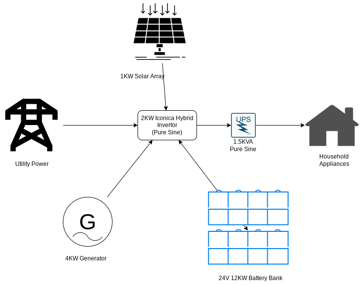
Keep in mind that this is only a small diy proof of concept rig for learning purposes as well as to get some autonomy (prepper mindsed).
Oh, one last note here, the pic above has a generator icon in it because I took that into account when I wired everything and because I actually bought a generator 🙂 to wire to the rig. The generator itself is not actually wired at the moment because I don’t really have room to install it in a more “permanent” position but should the situation require it I can indeed wire the generator to the installation. The generator itself is nothing special (I got a fairly cheap one on Amazon that people working in construction would normally buy) but the thinking was to have some backup juice in case of a longer power outage and by design any leftover juice that it produces will be stored by the batteries (no household would use 4kw/h continuously but the generator will deliver that regardless so … why not store what’s not used for later? … )
I’ll tell you this, I enjoyed every stage of the project so far and standby for more as I’m sure that this is only the beginning 🙂